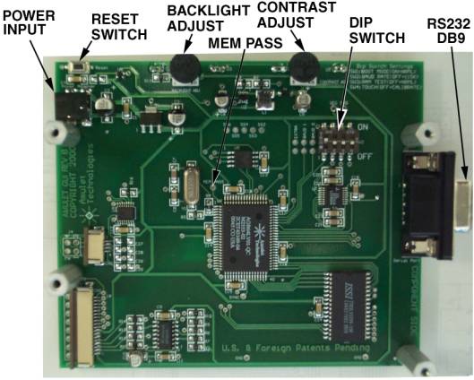
Figure 1. Amulet Easy GUI 3.8" board assembly, component side.
Figure 1. Amulet Easy GUI 3.8" board assembly, component side.
| PCB Size: | 4.25" x 3.58" |
| LCD: | Chip-on-glass, 3.48" x 2.72" (3.8" diagonal); 320 x 240, monochrome, black on white; viewable area 3.14" x 2.39" (76.79 x 57.59mm) |
| Dot Pitch: | 0.24 x 0.24mm |
| Dot Size: | 0.225 x 0.225mm |
| Touch Screen: | 4-wire resistive analog; active area is 80 x 62mm; utilizes full 320 x 240. NOTE: Since the touch screen is touch activated, do NOT allow your mounting hardware to apply any compression forces inside the active area! |
| Backlight: | LED Rimshot, always ON adjustable brightness. |
| Operating Temp.: | -10° to 60°C; rh>65% non-condensing |
| Storage Temp.: | -20° to 70°C |
| Power: | 5 to 10 VDC @100mA (9-volt battery and adapter supplied) |
| SRAM: | 128k-Bytes |
| Flash: | One 128k-Bytes (64k-Bytes available) |
| Serial Port: | One RS-232, 9-pin DIN, up to 115.2 Kbps |
|
|
Switch 1 -- Boot Mode Switch 2 -- Program Baud Rate Switch 3 -- RAM Test Switch 4 -- Touch Panel Mode |
Boot Mode (DIP switch 1) -- This switch is monitored during a reboot to determine the operational mode
of the controller board; ON is the normal mode and OFF is the FLASH program mode. Upon clicking on the Program FLASH button in the Compiler window, the Compiler will attempt to send out an auto "wake-up" message to the Amulet controller. If the page currently being displayed is set up to use the same baud rate using the META tag (if META is not present, the default is 115200) as the Compiler's uP comm rate,
then the Amulet controller will change to a generic "Please wait while programming flash..." screen and commence programming. If the page has a baud rate different than what the Compiler is set to, then you should
set the uP comm rate in the Settings->RS232 dialog
box to match the baud rate set by the META tag. This will allow the HTMLCompiler
to wake up the Amulet at one baud rate and then program it at another baud
rate. The only time you should have to set Switch 1 to OFF (program mode) is
when the project you compiled locks up the Amulet OS to the point where it won't
accept the wake up message or if the Amulet OS has been corrupted and you need
to reload the OS.
Program Baud Rate (DIP switch 2) -- This switch sets the baud rate used during a Flash Reprogram. The ON position sets the hardware to 19,200 baud; OFF sets the hardware to 115,200 baud. This setting must match the baud rate selected in the Easy GUI HTMLCompiler software.
RAM Test (DIP switch 3) -- Turn this switch ON and then reboot the controller board to auto-execute a RAM test. A RAM test failure will result in a zero (0) volt signal on the MEM PASS test pad on the board; a pass will result in a 3.3 volt signal. The switch must be returned to the normal mode (OFF) before the next reboot to continue normal operation.
Touch Panel Mode (DIP switch 4) -- This switch should remain ON during normal operation. Turn this switch
OFF and then reboot the controller board to begin a touch panel calibration. The controller will display a series
of three calibration targets. Use a stylus to touch the center of each target. If necessary,
the controller will repeat the calibration. When calibration is complete, the controller will return to normal
operation. The switch must be returned to the normal mode (ON) before the next reboot to continue normal operation.
|
|
CAUTION: Do not reverse the polarity on the power input. Doing so will permanently damage the module and invalidate your warranty. |
Figure 2. Power Input Power is applied to the 1.3mm connector.
Power requirement 5 to 10 VDC @100mA
Reset Switch -- This momentary pushbutton switch resets the Easy GUI controller chip as well as LCD power.
The serial parameters for communications between the Easy GUI client and the server are, as follows:
Baud Rate: 9600, 19200, 57600, or 115200bps
Parity: None
Data Bits: 8
Stop Bits: 1
See Communications Protocol for more information.
Although the touch panel is factory calibrated, you may need to recalibrate it from time to time. The calibration data is stored in a FLASH ROM location called the Operating System (OS) resource segment. For this reason, you must always recalibrate the touch panel after restoring or updating the OS. To perform a touch panel calibration through hardware, proceed as follows:
Switch 1 ON Boot Mode
Switch 2 OFF Flash Mode Baud Rate
Switch 3 OFF RAM Test
Switch 4 OFF Touch Panel Mode
Touchscreen calibration can also be entered via software, by using the Amulet:calibrate() function call. See the calibrate example for more information.